
Safety in machinery design requires a rigorous, systematic approach to identify hazards and mitigate risks before a piece of equipment ever hits the factory floor. ISO 12100:2010 serves as the foundational Type-A international standard for machinery safety. It outlines an iterative engineering lifecycle where risk assessment feeds directly into a strict risk reduction strategy.
When designing or modifying complex machinery, engineers cannot treat risk assessment as a compliance exercise. It must actively drive the mechanical, electrical, and control system architecture.
The Risk Assessment Process
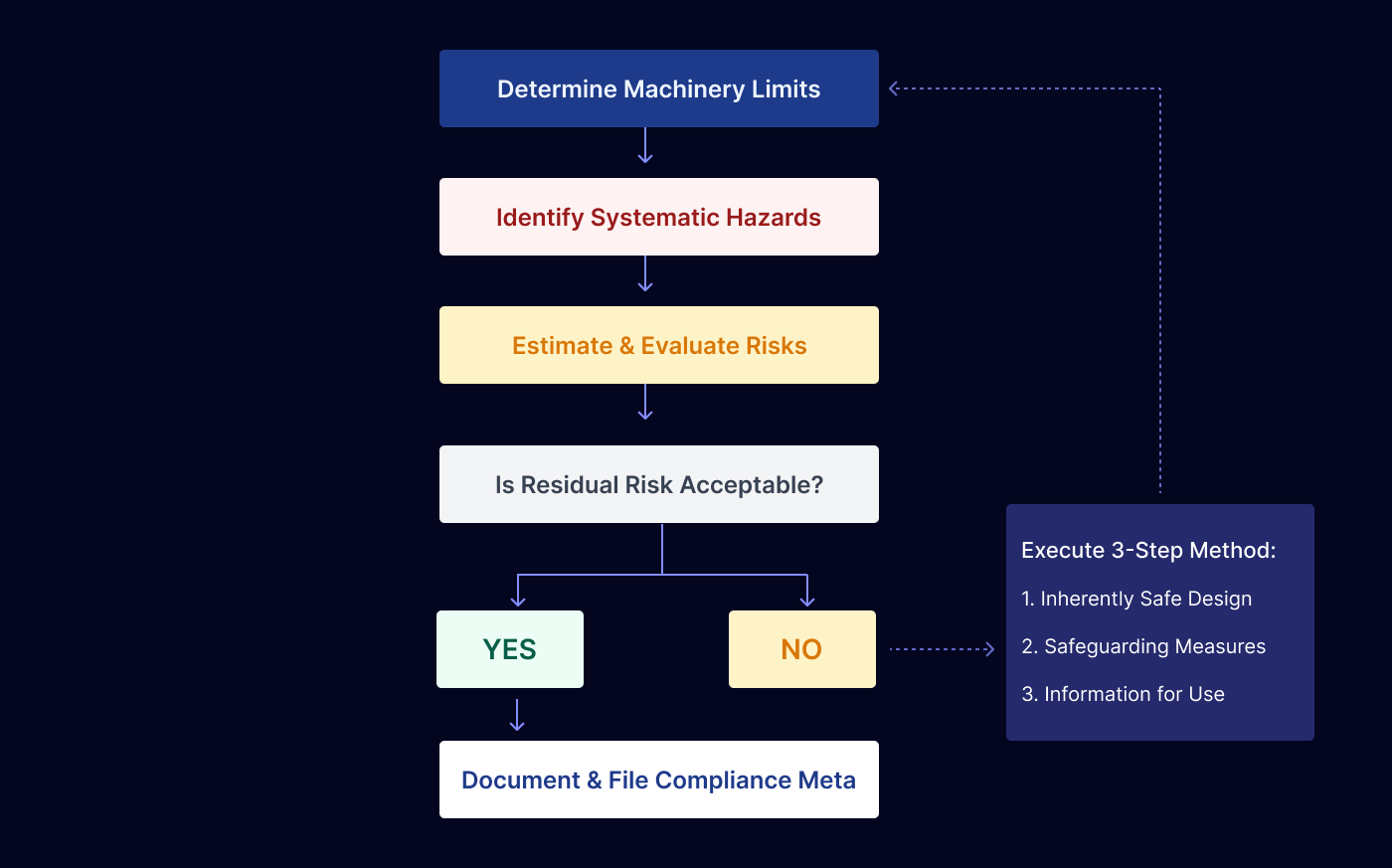
Under ISO 12100:2010, risk assessment is divided into a structured four-stage process: machine limits determination, hazard identification, risk estimation, and risk evaluation.
1. Machine Limits Determination (Clause 5.3)
The engineering assessment begins by establishing the absolute operational boundaries and parameters of the machine. This context must be fully documented before any hazard analysis takes place and includes:
Use Limits:
Defining the machine's intended use, predictable operational modes (including setup, maintenance, cleaning, and teaching functions), and the consequences of foreseeable misuse.
Space Limits:
Documenting the full range of motion, operator intervention zones, maintenance access requirements, and the footprint of interfacing subsystems.
Time Limits:
Establishing the expected life cycle of the machinery, the wear-and-tear parameters of safety-critical components, and mandatory preventive maintenance intervals.
Environmental Limits:
Accounting for temperature extremes, explosive atmospheres (ATEX zones), moisture, dust exposure, electromagnetic interference, and chemical vulnerabilities.
2. Systematic Hazard Identification (Clause 5.4)
Once limits are locked in, engineers must identify all potential hazards, hazardous situations, and hazardous events across all phases of the machine's life cycle. Relying solely on a walkthrough is insufficient; engineers must actively analyze design schematics, process loops, and failure modes.
Machinery hazards must be categorized into distinct engineering domains:
Mechanical Hazards:
Crushing, shearing, cutting, entanglement, drawing-in, impact, or high-pressure fluid injection.
Electrical Hazards:
Direct or indirect contact with live voltage components, electrostatic discharge, or thermal radiation.
Thermal Hazards:
Contact with extreme temperature surfaces or materials leading to burns or frostbite.
Ergonomic Hazards:
Physical strain, poor visibility, or inadequate operator interfaces causing human error or injury.
Environmental/Operational Hazards:
Failures in control systems, power fluctuations, or structural instability under load.
3. Risk Estimation Parameters (Clause 5.5)
The risk associated with any identified hazard is calculated as a function of the severity of the potential harm combined with the probability of that harm occurring.

To compute an accurate risk index, engineers evaluate four critical real-world parameters:
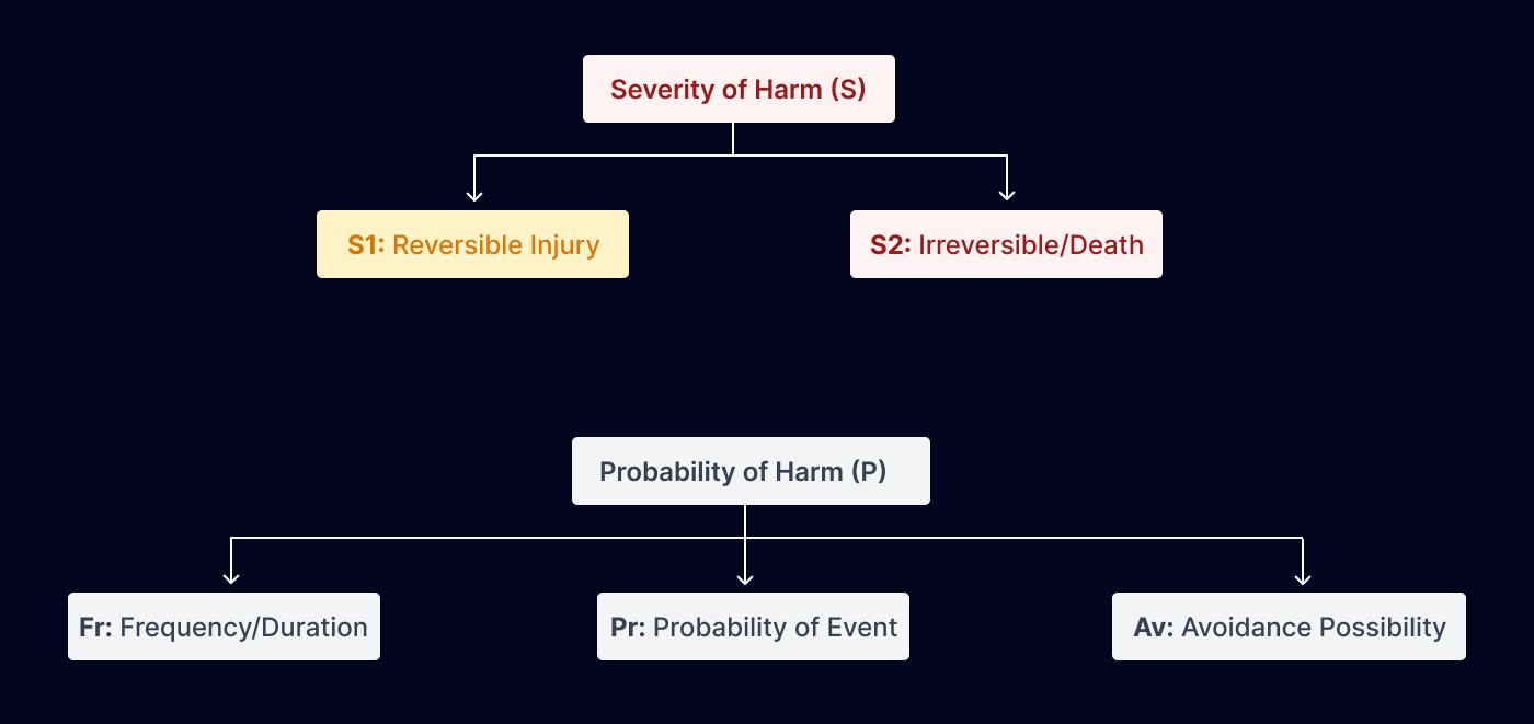
Severity of Harm ($S$):
Evaluated from minor, reversible injuries (S1) up to catastrophic, permanent disability or death (S2).
Frequency and Duration of Exposure (Fr):
Tracking how often operators must enter the hazard zone (e.g., hourly during reloading or monthly during maintenance) and for how long.
Probability of Occurrence of the Hazardous Event (Pr):
Factoring in component failure rates, reliability metrics, and historical data from similar systems.
Possibility of Avoiding or Limiting Harm (Av):
Assessing if the hazard develops slowly enough for an operator to recognize it and react, or if physical design characteristics prevent escape.
4. Risk Evaluation (Clause 5.6)
Following estimation, the calculated risk index is compared against predefined risk acceptance criteria. If the risk does not meet acceptable limits or falls outside the As Low As Reasonably Practicable (ALARP) threshold, engineers must execute a structured risk reduction loop.
The Mandatory 3-Step Risk Reduction Hierarchy
When a design requires mitigation, ISO 12100 dictates a strict, non-negotiable three-step method. Engineers cannot skip directly to warning labels or personal protective equipment (PPE); they must address risks in order of the hierarchy.
Step 1: Inherently Safe Design Measures
The most effective way to eliminate risk is to engineer the hazard completely out of the system at the source. This is the priority phase of machinery design.
Engineering Examples:
Redesigning mechanism geometry to eliminate pinch points or shearing zones; reducing operating velocities or hydraulic pressures below hazardous thresholds; optimizing mechanical balance to prevent tipping; and selecting low-voltage DC control architectures to eliminate electrical shock hazards.
Step 2: Safeguarding and Complementary Protective Measures
If hazards cannot be designed out without compromising the machine's core function, engineers must integrate physical and electronic safety-related control functions.
Engineering Examples:
Installing heavy-duty physical perimeter fencing with dual-channel safety interlocked gates; deploying Type 4 safety light curtains or safety laser scanners to monitor active operator loading zones; and integrating safety-rated monitored stop circuits tied to dedicated emergency stop buttons. All electronic safeguarding systems must achieve the required Performance Level (PL) under ISO 13849-1 or Safety Integrity Level (SIL) under IEC 62061 as indicated by the risk evaluation.
Step 3: Information for Use
The final layer of protection addresses any remaining residual risk that cannot be neutralized by Steps 1 or 2. This layer must never act as a substitute for proper safeguarding or inherently safe design.
Engineering Examples:
Permanently mounting standardized safety signs and hazard symbols directly on high-voltage or thermal enclosures; integrating visual or audible alerts into the HMI interface to flash during machine startup; and writing technical manuals that specify mandatory PPE, lock-out/tag-out (LOTO) protocols, and technician training requirements.
The ISO 12100 Iterative Engineering Loop
The integration of risk assessment and risk reduction forms a continuous loop that must be executed until all residual risks are thoroughly validated as acceptable.
Verification, Validation, and Documentation
A risk assessment is incomplete until compliance with ISO 12100 is fully documented in a technical file. This documentation acts as the definitive safety record for the product and must include:
Detailed Hazard Logs:
A complete matrix tracking every identified hazard, its root cause, and its lifecycle phase.
Risk Evaluation Metrics:
Clear documentation of the assumptions, risk estimation models, and formulas used to calculate initial risk ratings.
Mitigation Records:
Explicit tracking of design modifications, control system specs, FMEA sheets, and safety function parameters.
Validation Records:
Physical test data, calculation files, and stopping-time measurements confirming that integrated safeguarding measures operate within acceptable parameters and effectively control residual risk.